OMRON

LD / HD Series

หุ่นยนต์เคลื่อนที่อัตโนมัติ (AMRs) มีฟังก์ชั่นการทำแผนที่ และนำทางด้วยตัวเอง ติดตั้งง่ายสามารถปรับให้เข้ากับงานที่หลากหลาย

MADE FOR INDUSTRY ผลิตมาเพื่องานอุตสาหกรรม
ด้วยฐานผู้ใช้งานที่ใหญ่ที่สุดในโลก หุ่นยนต์เคลื่อนที่ OMRON ถูกนำไปใช้งานอุตสาหกรรมต่างๆ
มีการทำงานที่หลากหลาย กว่า 1.000 รูปแบบ


Mobile Robots


FLEXIBLE FUNCTIONALITY ฟังก์ชั่นที่ยืดหยุ่น
Mobile Solutions ของ OMRON ที่ฟังก์ชั่นการทำงานที่หลากหลาย สามารถปรับให้เข้ากับงาน และแอพพลิเคชั่นต่างๆได้
นอกจากนี้ยังสามารถปรับขนาด เพื่อให้เติบโตไปพร้อมกับธุรกิจของคุณได้อีกด้วย


ช่วยขยายธุรกิจของคุณ

  • ปรับเปลี่ยนเลย์เอาต์เพื่อเพิ่มประสิทธิภาพการผลิต

ปรับให้เข้ากับสภาพแวดล้อมที่เปลี่ยนไปได้

  • Assembly stations
  • Clean rooms
  • Order fulfillment
  • Loading docks
  • Stock rooms

Mobile Robots


OMRON MOBILE SOLUTION
หุ่นยนต์เคลื่อนที่ของ OMRON ถูกสร้างขึ้นเพื่อจัดการงานขนส่ง-เคลื่อนย้าย การจัดส่ง และการกำหนดเส้นทาง
ช่วยเพิ่มประสิทธิภาพและให้การทำงานที่ง่ายขึ้น เพื่อให้พนักงานสามารถไปทำงานที่ยากหรือซับซ้อนกว่า


OMRON ให้บริการที่มากกว่าหุ่นยนต์ เราส่งมอบระบบนิเวศที่เต็มไปด้วยเทคโนโลยีอัตโนมัติ (Automation Technology) Solution ที่ดีที่สุดจากแหล่งเดียว
ยินดีต้อนรับสู่ Fleet Operations Workspace (FLOW)

Mobile Robots


OMRON INDUSTRIAL AUTOMATION SOLUTION
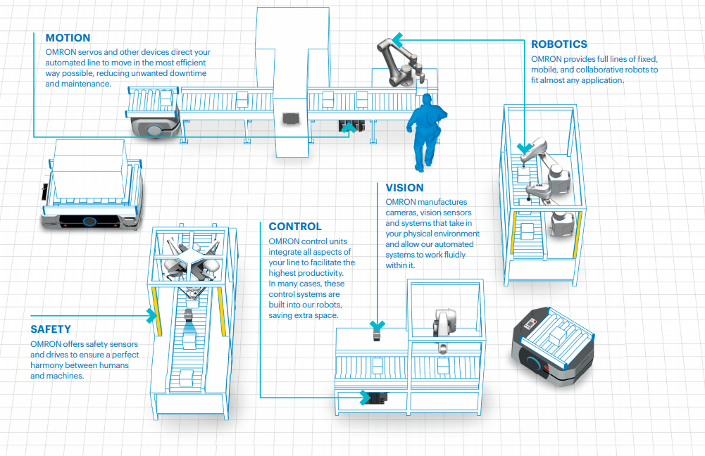
คุณต้องการมากกว่าอุปกรณ์ที่มีฮาร์ดแวร์ขั้นสูง คุณต้องมีระบบขนส่งวัสดุอัตโนมัติที่ยืดหยุ่นเพียงพอที่จะพัฒนาไปพร้อมกับความต้องการที่เปลี่ยนแปลงไป เทคโนโลยีระบบอัตโนมัติเต็มรูปแบบของ OMRON จะช่วยเติมเต็มสายการผลิตของคุณ


ในฐานะผู้นำด้านระบบอุตสาหกรรมแบบอัตโนมัติ OMRON นำเสนอผลิตภัณฑ์ที่ช่วยให้ผู้ผลิต ตอบสนองความต้องการในการทำ Mass Customization และแก้ไขปัญหาที่เกี่ยวข้องกับต้นทุนแรงงานที่เพิ่มขึ้น จากปัญหาการขาดแคลนแรงงาน

นอกเหนือจากหุ่นยนต์เคลื่อนที่แล้ว OMRON ยังมีอุปกรณ์และเครื่องมือทีาใช้ในระบบอัตโนมัติที่หลากหลาย ซึ่งมีตั้งแต่ Control components และ Vision sensors ไปจน Controllers และ Servomotors
รวมถึง อุปกรณ์safety และ หุ่นยนต์ fixed robots ด้วย


Mobile Robots


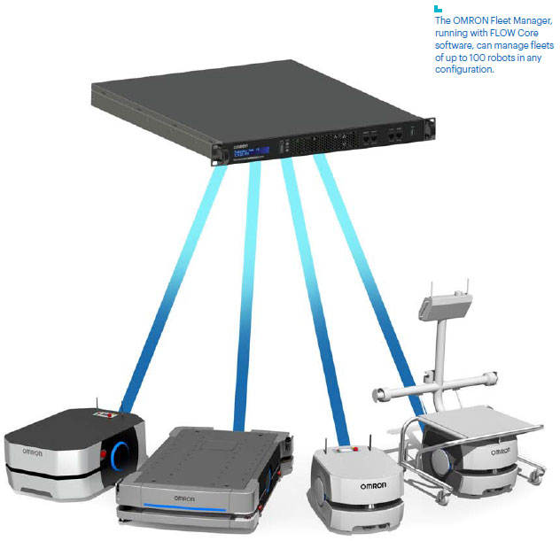
POWERFUL FLEET MANAGEMENT
OMRON Fleet Operations Workspace (FLOW) Core

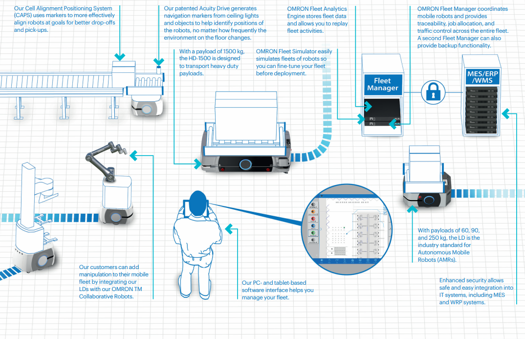
โซลูชัน OMRON Fleet Operations Workspace (FLOW) มีระบบการจัดการยานพาหนะอัจฉริยะ ที่สามารถตรวจสอบตำแหน่งหุ่นยนต์ สภาพจราจร และคำของานต่างๆ เพื่อให้มั่นใจว่าโรงงานของคุณ ทำงานได้อย่างมีประสิทธิภาพสูงสุด

โดยการทำงานแบบอัตโนมัติของหุ่นยนต์ FLOW Core solution ของเรา ยังช่วยลดการเขียนโปรแกรมในระบบปฏิบัติการการผลิต (MES)
หรือระบบการวางแผนทรัพยากรองค์กร (ERP)
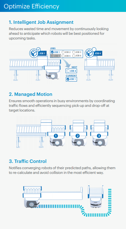
  • แสดงคิวงาน
  • จัดลำดับความสำคัญของงาน
  • เลือกเส้นทางที่เร็วที่สุดตามการจราจรของมนุษย์และหุ่นยนต์
  • ระบุเส้นทางที่ถูกบล็อกและสร้างเส้นทางใหม่
  • เพิ่มประสิทธิภาพการมอบหมายงาน
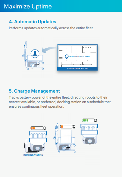
  • เพิ่มประสิทธิภาพการชาร์จแบตเตอรี่

Mobile Robots


OMRON FLEET MANAGER


Mobile Robots

Mobile Robots

Mobile Robots


PRECISE PERFORMANCE

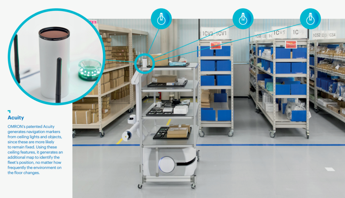
Navigation นำทางที่ปลอดภัยและชาญฉลาดของเรา เป็นผู้นำในอุตสาหกรรมทั้งด้านความเร็วและความแม่นยำ
เมื่อใช้ Multiple systems หุ่นยนต์ของเราจะเรียนรู้มากยิ่งขึ้นหลังจากติดตั้งแล้ว หุ่นยนต์ทุกตัวใน Fleet จะทำหน้าที่เป็นเซ็นเซอร์ในการทำแผนที่จำลองสภาพแวดล้อม และปรับปรุงการทำงาน ตั้งแต่การเดินทางในที่แคบ ๆ ไปจนถึงการวางแผนเส้นทางที่มีประสิทธิภาพสูงสุด

  • การหลีกเลี่ยงสิ่งกีดขวางแบบไดนามิก
  • เวลาในการนำทางเร็วขึ้น
  • การขับขี่ที่นุ่มนวลขึ้น
  • ความเร็วในการเข้าสู่เป้าหมายที่รวดเร็ว
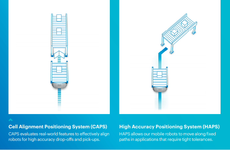
  • การจัดตำแหน่งที่เหนือกว่าที่เป้าหมาย
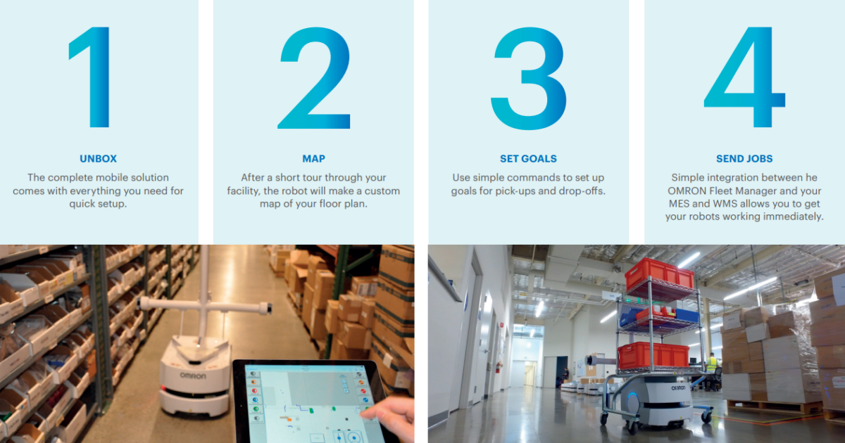
Mobile Robots Mobile Robots


EASY INSTALL

หุ่นยนต์เคลื่อนที่ OMRON นั้นง่ายต่อการเริ่มต้นและใช้งาน ไม่ต้องมีการก่อสร้างเพื่อการติดตั้งเพิ่มเติม เช่นการติดตั้งแม่เหล็ก และการเขียนโปรแกรมขั้นต่ำ นอกจากนี้ซอฟต์แวร์ของเรายังทำงานร่วมกับระบบอื่น ๆ ของคุณเพื่อให้คุณสามารถแก้ปัญหาและทำงานได้ในเวลาอันสั้น

  • ไม่ต้องมีการก่อสร้างเพื่อการติดตั้งเพิ่มเติม
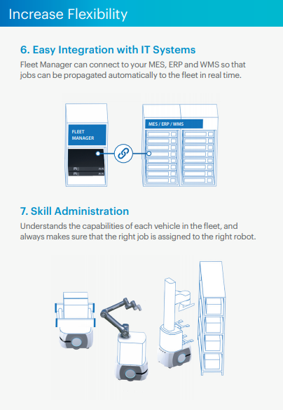
  • ใช้งานร่วมกับ MES, ERP และ WMS ได้อย่างง่ายดาย
  • การรักษาความปลอดภัยขั้นสูง เพื่อให้สอดคล้องกับระบบ IT
  • การนำทางแบบอัตโนมัติ ไม่จำเป็นต้องมีเส้นทางแม่เหล็ก หรือ beacons ที่กำหนดไว้
  • อัปเดตซอฟต์แวร์อัตโนมัติทั่วทั้ง Fleet ในขณะที่ยังทำงานอย่างต่อเนื่อง

Mobile Robots


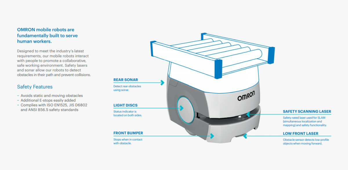
SAFE BY DESIGN
หุ่นยนต์เคลื่อนที่ OMRON ถูกสร้างขึ้นโดยพื้นฐาน เพื่อรองรับแรงงานมนุษย์

ออกแบบมาเพื่อตอบสนองความต้องการล่าสุดของอุตสาหกรรม หุ่นยนต์เคลื่อนที่ของเราโต้ตอบกับผู้คน เพื่อส่งเสริมสภาพแวดล้อมการทำงานร่วมกันและปลอดภัย
เลเซอร์นิรภัย และโซนาร์ ช่วยให้หุ่นยนต์ตรวจจับสิ่งกีดขวางในเส้นทาง และป้องกันการชนกัน

Safety Features

  • หลีกเลี่ยงสิ่งกีดขวางที่อยู่นิ่งและเคลื่อนที่
  • เพิ่มตัว E-stop เข้ามาได้ง่าย
  • เป็นไปตามมาตรฐานความปลอดภัย ISO EN1525, JIS D6802 และ ANSI B56.5


MID-SIZE CAPACITY Mobile Robots

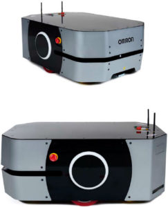
พบกับสมาชิกขนาดกลางของหุ่นยนต์เคลื่อนที่ตระกูล OMRON

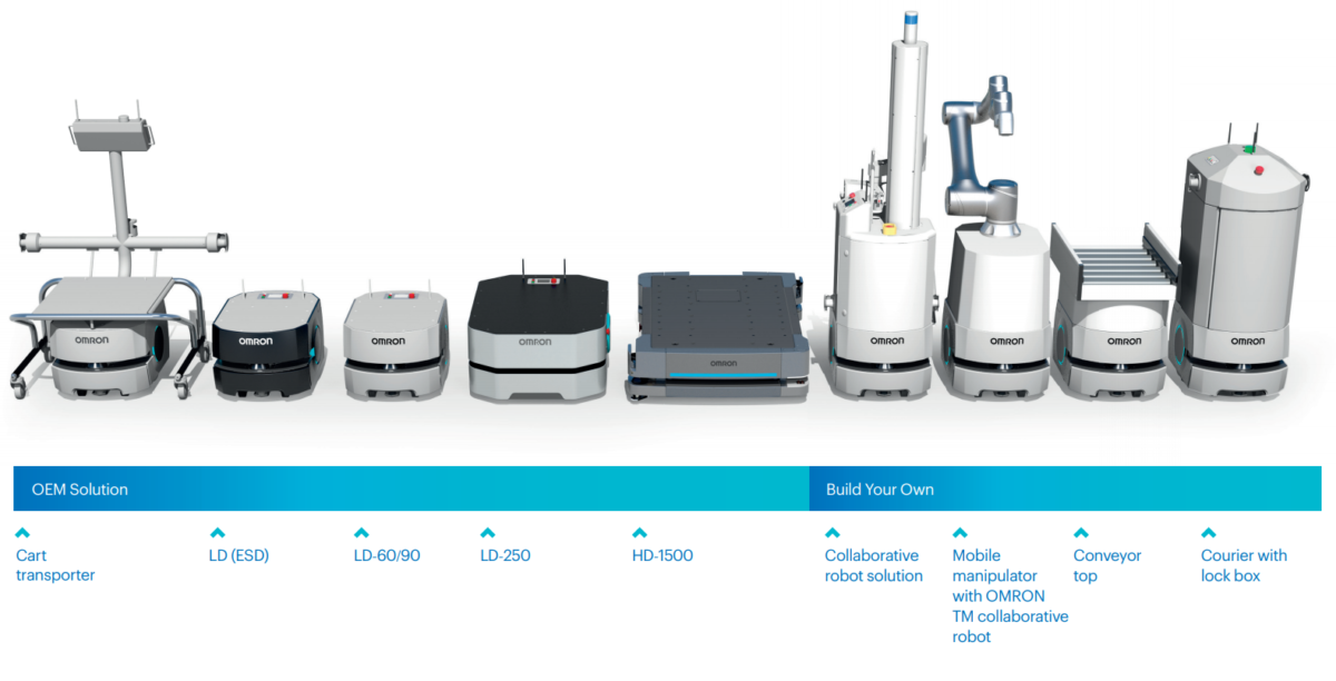
OMRON มีความภูมิใจที่จะประกาศเปิดตัว LD-250 ซึ่งเป็นหุ่นยนต์เคลื่อนที่ขนาดกลางของเราที่มีน้ำหนักบรรทุก 250 กก.

LD-250 มีพื้นฐานมาจากเทคโนโลยีที่ผ่านการทดสอบ และพิสูจน์แล้ว ซึ่งใช้ใน LD-90 หุ่นยนต์ชั้นนำของอุตสาหกรรม ด้วยความสามารถในการรับน้ำหนักที่สูงขึ้น และผิวโลหะที่แข็งขึ้น ลูกค้าสามารถขนชิ้นงานใส่โรบ็อตได้มากขึ้น ทำให้รอบการเดินทางน้อยลงด้วย

ทำงานร่วมกับกลุ่มยานยนต์ Integrated OMRON mobile fleet หุ่นยนต์ LD-250 ช่วยให้คุณสามารถเพิ่มประสิทธิภาพ ในการจัดการ Traffic การจัดการแบตเตอรี่ และการกำหนดเส้นทางของยานพาหนะด้วย Fleet ที่หลากหลายมากขึ้น


Mobile Robots

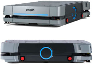
HEAVY DUTY TRANSPORT 
พบกับสมาชิกที่แข็งแกร่งที่สุดของตระกูลหุ่นยนต์เคลื่อนที่ของ OMRON

OMRON มีความภูมิใจที่จะประกาศเปิดตัว HD-1500 ซึ่งเป็นหุ่นยนต์เคลื่อนที่อัตโนมัติรุ่นล่าสุดของเราที่มี รับน้ำหนักบรรทุกได้ถึง 1,500 กก.

ความสามารถในการรับน้ำหนักที่สูงขึ้นช่วยให้ลูกค้าสามารถทำงานใหม่ ๆ ที่ไม่เคยทำได้มาก่อนได้ เช่นการขนส่งสินค้าขนาดเท่าพาเลท ขนส่งบล็อกเครื่องยนต์ และสินค้า หรือ อุปกรณ์หนักอื่น ๆ

HD-1500 ยังสามารถทำงานอัตโนมัติ ที่เแบบเดิมใช้รถยกในการทำ ช่วยลดความเสี่ยงในการบาดเจ็บ

ทำงานร่วมกับกลุ่มยานยนต์ Integrated OMRON mobile fleet หุ่นยนต์ HD-1500 ช่วยให้คุณมีตัวเลือกมากขึ้น ในแง่ของการพัฒนา Mobile solution ที่ปรับแต่งได้มากที่สุดสำหรับโรงงานของคุณ


Key Features

  • รับน้ำหนักได้ 1,500 กก
  • ใช้เทคโนโลยีที่ได้รับการยอมรับแบบเดียวกับที่ใช้ใน LD series.
  • ความปลอดภัยแบบ 360 ° ด้วยเทคโนโลยี LiDAR
  • ชาร์จแบตเตอรี่เต็มใน 35 นาที
  • ผิวโลหะที่แข็งแรง ทนต่อการกระทบกระเทือนที่หนัก และงานที่มากขึ้น

LD Series


Mobile Robots-LD Platform

LD-60, LD-90, ESD OEM, and Cart Transporter

Item LD-60, LD-90, ESD OEM Cart Transporter Note
37032-
[][][][][]
37042-
[][][][][]
37142-
[][][][][]
37162-
[][][][][]
Materials Polycarbonate
Dimension (L × W × H) 699 × 500 × 383 mm 894 × 1074 × 1394 mm* * Height includes WiFi antenna
Weight (with Battery) 62 kg 81 kg (Vehicle)/23 kg (Cart)
Envi-
ronment
Ambient
temperature
5 to 40 °C
Ambient humidity 5 to 95 % (non-condensing)
Operating
Environment
Indoor usage only, no excessive dust, no corrosive gas Direct sunlight may cause
safety laser false positive
IP rating IP20
Cleanroom rating Fed Class 100, ISO Class 5 None
Floor
Condi-
tions
Floor
Requirements
Linoleum, epoxy, or concrete (no water, no oil, no dirt)
Minimum floor
flatness
FF25 (ACI 117 standard)* * ACI 117 is the American
Concrete Institute standard for
concrete floors.
FF is flatness, FL is the level.
Higher FF numbers represent
flatter floors. FF25 is a fairly
lenient specification.
Traversable step 15 mm
max. *1
10 mm
max. *1
5 mm max.
*2
5 mm max.
*2
*1 A speed of 250-300 mm/s
and 250 mm/s, for the LD-60
and LD-90, is required for these
steps. Faster or frequent driving
over such steps or gaps will
shorten the lifespan of the
drivetrain components. Lower
speeds may not traverse the
step. Steps should have
smooth, rounded profiles.
*2 The Cart Transporter with a
cart is capable of driving over a
gap or step of 5 mm at a speed
of 250 mm/s, but this should not
be regarded as normal use.
Regular driving over such gaps
or steps will shorten the lifespan
of the drivetrain components.
Traversable gap 15 mm
max.
15 mm
max.
5 mm max.
*2
5 mm max.
*2
Climb grade Below 1: 12 (60 kg max.)
Flat floor only (over 60 kg)
Flat floor only
Navi-
gation
Routing Autonomous routing by localizing with safety scanning
laser based on environment mapping
Environmental
map making
method
Scan by walking the mobile robot through the
environment, and upload the scan data in the
MobilePlanner
Payload Maximum
Weight
60 kg 90 kg 105 kg * 130 kg * * Excluding cart weight
Mobility Maximum Speed 1800 mm/s 1350 mm/s 1350 mm/s 900 mm/s
Maximum
Rotation Speed
180°/s 180°/s 100°/s
Stop Position
Repeatability
Basic: ±100 mm position
Standard Target: ±25 mm position, ± 2° rotation
*±10 mm position, ±0.5° rotation
with option, (High Accuracy
Positioning System)
±8 mm position, ±1° rotation
with option, (Cell Alignment
Positioning System)
Drive
wheel
Materials Non-marking nylon foam-filled rubber, non-conductive
Size 200 dia. × 50 mm nominal, 2 wheels
Passive
caster
Materials Conductive thermoplastic rubber on polyolefin
Size 75 dia. × 41 mm nominal, 4 casters
Power Battery 22-30 VDC
Capacity 72 Ah Battery cell nominal capacity
Run Time 15 hours (continuous) approx. With no payload condition
Recharge Time 4 hours (5:1 ratio) approx.
Battery Life
Cycles
2,000 recharge cycles (battery cell nominal)
Charging Method Automatic / manual
Auxiliary Power 5 VDC±5%, 1 A switched Aux power
12 VDC±5%, 1 A switched Aux power
20 VDC±5%, 1 A switched Aux power
22-30 VDC, 4 A switched × 2
22-30 VDC, 10 A switched*
22-30 VDC, 10 A safe, switched*
5, 12, 20, and 22-30 VDC
power can be provided to
external devices
* 10 A switched and 10 A safe,
switched share the 10 A of
current
Standard Harmonized
Standard
EN IS0 12100 / EN ISO 13849-1 / EN 60204-1
Relevant
Standard
EN 1525 / ANSI B56.5
Wireless 802.11 a/b/g/n/ac
Safety
Features
Safety Scanning
Laser
1 at front
Class 1
PLd safety per ISO13849-1
15 m maximum range
240° field of view
Emergency Stop 1 at operator panel 1 at HMI post touchscreen,
1 at operator panel
Rear Sonar 2 at rear, 2 m range Each pair includes one emitter
and one receiver working
together
Front Bumper 1 at front of platform, 2 pairs of sensors
Low Front Laser 1 at front of platform
Class 1
4 m maximum range
126° field of view
Side Laser Option * 2 on horizontal tubes of
HMI post Class 1
4 m maximum range
270° field of view
* 2 on sides of payload
structure, user-mounted
Indicators Light disc in each side Light disc in each side,
beacon on HMI post
Speaker 3.5 in., 80 W max.
Operator
Interface
Screen/
Touch Panel
3.5 in. TFT 320 × 240
pixels, color screen
7.0 in. TFT LCD touch
panel, 18/24 bit RGB
Button On button: green
Off button: red
Brake-release button:
orange
Keyswitch (disabled off
button) *
On button: green
Off button: red
Brake-release button:
orange
Keyswitch (disabled off
button) *,
Latch button, unlatch button
* Key switch can be used to
disable the off button to avoid
accidental shutdown or
tampering.
User
Interface
Wireless 802.11 a/b/g/n/ac
Ethernet Port 1 x user LAN, 1 x maintenance LAN, Auto-MDIX
Serial RS-232 × 2
Digital I/O 16 inputs, 16 outputs
Analog I/O 8 inputs (0 to 30 V), 4 outputs (0-20 V)
Audio Digital audio out, audio in / audio out
Cart
Latching
Latching Method Not available Automatic

LD-250, ESD OEM

Item LD-250, ESD OEM Note
37222-[]000[]
Materials Aluminum
Dimension (L × W × H) 963 × 718 × 383 mm * Height to top plate.
Weight 148kg (with battery), 129kg (without battery)
Envi-
ronment
Ambient
temperature
5 to 40 °C
Ambient humidity 5 to 95 % (non-condensing)
Operating
Environment
Indoor usage only, no excessive dust, no corrosive gas Direct sunlight may cause safety
laser false positive
IP rating IP20
Cleanroom rating Fed Class 100, ISO Class 5
Floor
Condi-
tions
Floor
Requirements
Linoleum, epoxy, or concrete (no water, no oil, no dirt)
Minimum floor
flatness
FF25 (ACI 117 standard)* * ACI 117 is the American
Concrete Institute standard for
concrete floors.
FF is flatness, FL is the level.
Higher FF numbers represent
flatter floors. FF25 is a fairly
lenient specification.
Traversable step 10 mm max.* * For LD-250, the robot should
traverse the 10mm step at 600
mm/s or slower for best
performance of the laser and
battery.
Traversable gap 15 mm max.
Climb grade Flat floor only (full payload)
Navi-
gation
Routing Autonomous routing by localizing with safety scanning
laser based on environment mapping
Environmental
map making
method
Scan by walking the mobile robot through the
environment, and upload the scan data in the
MobilePlanner
Payload Maximum Weight 250 kg
Mobility Maximum Speed 1200 mm/s
Maximum
Rotation Speed
120°/s
Stop Position
Repeatability
Basic: ±100 mm position
Standard Target: ±25 mm position, ± 2° rotation
*±10 mm position, ±0.5° rotation
with option, (High Accuracy
Positioning System)
±8 mm position, ±1° rotation
with option, (Cell Alignment
Positioning System)
Drive
wheel
Materials Aluminum with polyurethane tread
Size 200 dia. × 50 mm nominal, 2 wheels
Passive
caster
Materials Static dissipative
Size 127 dia. × 51 mm nominal, 4 casters
Power Battery 22-30 VDC
Capacity 72 Ah Battery cell nominal capacity
Run Time 13 hours (continuous) approx. With no payload condition
Recharge Time 4 hours (4:1 ratio) approx.
Battery Life Cycles 2,000 recharge cycles (battery cell nominal)
Charging Method Automatic / manual
Auxiliary Power 5 VDC±5%, 1 A switched Aux power
12 VDC±5%, 1 A switched Aux power
20 VDC±5%, 1 A switched Aux power
22-30 VDC, 4 A switched × 2
22-30 VDC, 10 A switched*
22-30 VDC, 10 A safe, switched*
5, 12, 20, and 22-30 VDC power
can be provided to external
devices
* 10 A switched and 10 A safe,
switched share the 10 A of
current
Standard Harmonized
Standard
EN IS0 12100 / EN ISO 13849-1 / EN 60204-1
Relevant
Standard
EN 1525 / ANSI B56.5
Wireless 802.11 a/b/g/n/ac
Safety
Features
Safety Scanning
Laser
1 at front
Class 1
PLd safety per ISO13849-1
3 m maximum radius from laser for safety zones
40 m radius for general sensing
240° field of view
Emergency Stop 1 at operator panel, 1 on each side (3 total)
Rear Sonar Time of flight (TOF) sensors
Low Front Laser 1 at front of platform
Class 1
4 m maximum range
126° field of view
Side Laser Option* * 2 on sides of payload structure,
usermounted
Indicators Light disc in each side
Speaker 3.5 in., 80 W max.
Operator
Interface
Screen/
Touch Panel
3.5 in. TFT 320 × 240 pixels, color screen
Button On button: green
Off button: red
Brake-release button: orange
Keyswitch (disabled off button)*
* Key switch can be used to
disable the off button to avoid
accidental shutdown or
tampering.
User
Interface
Wireless 802.11 a/b/g/n/ac
Ethernet Port 1 x user LAN, 1 x maintenance LAN, Auto-MDIX
Serial RS-232 × 2
Digital I/O 16 inputs, 16 outputs
Analog I/O 8 inputs (0 to 30 V), 4 outputs (0-20 V)
Audio Digital audio out, audio in / audio out
Cart
Latching
Latching Method Not available


MobilePlanner Software

Operating System Windows 10 (32-bit/64-bit version)
CPU 1.5 GHz dual-core CPU recommended
Main Memory 1.5 GB min. (4 GB min. recommended)
Hard Disk At least 200 MB of available space
Video Memory 256 MB min.
Display XGA 1024 × 768, 16 million colors
Supported Languages English, Japanese, German, French, Italian, Korean,
Spanish, Simplified Chinese, Traditional Chinese


EM2100 Appliance

Part Numbers 20271-900 (Primary Fleet Manager)
20271-901 (Secondary Fleet Manager)
20271-903 (Bundle, Fleet Simulator)
Dimensions- W × D × H 430 × 495.3 × 43.7 mm
Weight 9.1 kg
Mounting method 1U rack mount in a standard
19-inch equipment rack
Power Supply 100-240 VAC (typical 100 W)
Power Consumption 200W max.
Operating Temperature 10 to 35 °C
Storage Temperature -25 to 60 °C
Operating Humidity 8 to 90%, non-condensing
Storage Humidity 5 to 95%, non-condensing
Chassis protection class IP20
CPU Intel® Xeon® CPU
Main Memory 32 GB DDR3
Storage 60 GB SSD
Archive Storage 4 TB HDD
Communication port 10/100/1000 Ethernet × 4, USB × 4, VGA
Status Display Multi-segment LCD


High Accuracy Positioning System

Part Number 13660-[]00 (LD-60/90/105CT/130CT)
21374-[]00 (LD-250)
Sensor Depth 30 mm
Width 160 mm
Rating IP64
Environment -40 to 85 °C
LEDs Power, tape present, left marker, right marker
Magnetic Tape Width 25 mm
Orientation South up
Markers
(Magnetic Tape)
Width 25 mm
Length 300 mm min. for 500 mm/s drive speed
Orientation North up
Separation From Tape 15 – 30 mm
Connections Front Sensor RS232-1 (/dev/ttyUSB9) on the core
Rear Sensor RS232-2 (/dev/ttyUSB10) on the core
Power, Both Sensors Aux power using the included splitter cable


Acuity Localization

Part Number 13700-[]00
Field of View 140°
Power Input 12 VDC (±10%) supplied from platform through power connector
Power Consumption 3.3 W maximum


Cell Alignment Positioning System (CAPS)

Part Number 20271-805
Type Software license
Stop Position Accuracy ±8 mm position, ±1° rotation


Touchscreen

Part Number 13605-000
Touch Panel PCAP touch sensor, black-bordered cover lens
TFT Display TFT LCD panel, 18/24 bit RGB parallel interface,
7.0 in. WVGA – wide viewing angles, 5-touch
Backlight Constant current LED supply
Power Input 5 VDC supplied through power connector
Power Consumption 6.5 W maximum


Call/Door Box

Part Number 13029-802
Dimensions- W × D × H 141.4 × 74.7 × 30 mm
Weight 190 g
Mounting method Mount to the provided wall frame with four screws
Power Supply 12 VDC
Power Consumption 0.5 A, 6 W typical
WiFi IEEE 802.11 a/b/g/n
Communication Port Ethernet
I/O Input × 2, output × 2 (30 VDC, 2 A max.)


Battery

Part Number 20452-000
Run Time (No Payload) 15 hours (continuous) approx. (LD-60/90)
13 hours (continuous) approx. (LD-250)
Weight 19 kg
Voltage 22-30 VDC
Capacity 72 Ah (battery cell nominal)
Recharge Time 4 hours approx.
Life Expectancy 2,000 times 80% DOD (battery cell nominal),
7 years, approx., 16 hrs/day, 5 days/wk
4 years, approx., 19/7 (full-time)


Docking Station

Part Number 12477-0[]0
Current 8 A*1
Contacts 2
Power 100 to 240 VAC, 50 to 60 Hz
Power Consumption 800 W
Humidity 5 to 95 %, non-condensing
Temperature 5 to 40°C
Dimensions (W × D × H) 349 × 369 × 315 mm
495 × 495.5 × 317 mm (with floor plate)
Weight 8.2 kg
Mounting Wall bracket, directly to floor, or on floor with floor plate
Indicators Power on: blue
Charging: yellow
Connector For out-of-platform battery charging

*1 Thermal fuse in AC power switch (10 A time-lag fuse at switch for legacy dock)


Joystick

Part Number 13558-000
Weight 0.55 kg
IP Rating IP56


Cart

Part Number 75020-000
Dimensions (L × W × H) 592 × 846 × 480 mm
Weight 23 kg
Rating ESP-rated
Passive Casters 2 front, 2 rear, spring-loaded
Caster Diameter 100 mm nominal
Caster Brakes At 2 rear casters


HD Series


Mobile Robots-HD Platform

Item HD-1500 Note
Materials Structural components are made from low carbon steel and cast aluminum, nonstructural parts are aluminum
Dimension (L × W × H) 1696 x 1195 x 370 mm
Weight (with Battery) 585 kg
Environment Ambient temperature 5 to 40 °C
Ambient humidity 5 to 95% (non-condensing)
Operating
Environment
Indoor usage only, no excessive dust, no corrosive gas Direct sunlight may cause safety laser false positive
IP rating IP20
Floor Conditions Floor Requirements concrete, eproxy floor (no water, no oil, no dirt)
Minimum floor
flatness
FF25 (ACI 117 standard)* * ACI 117 is the American Concrete Institute standard for concrete floors.
Traversable step 10 mm max. Maximum speed of 500 mm/sec forward and 400 mm/ sec backwards
Traversable gap 15 mm max.
Climb grade level floor only. max. 3% incline
Navigation Routing Autonomous routing by localizing with safety scanning laser based on environment mapping
Environmental map
making method
Scan by walking the mobile robot through the environment, and upload the scan data in the MobilePlanner
Payload Maximum Weight 1500 kg
Mobility Maximum Speed 1800 mm/s
Maximum Rotation
Speed
60°/s
Stop Position
Repeatability
± 50 mm position* *±10 mm position, ±0.5° rotation with option, (High Accuracy Positioning System)
±8 mm position, ±1° rotation with option, (Cell Alignment Positioning System)
Drive wheels Materials Non-marking, static dissipative Polyurethane on steel rim.
Size 250 mm diameter x 80mm 2 wheels
Passive casters Materials Non-marking Polyurethane on cast iron 200 mm diameter x 50mm, 4 casters, 2 wheels each (8 wheels total)
Power Voltage 42VDC – 57VDC (52.8 V Nominal)
Capacity 70 Ah Battery cell nominal capacity
Run Time 12.5 hours (unloaded), 9 hours (full load)
Recharge Time 23.33 minutes (20 – 80%) or 39 minutes (0 – 100%)
Battery Life Cycles 9000 recharge cycles (battery cell nominal)
Charging Method Automatic / manual
Standard Harmonized Standard EN IS0 12100, EN ISO 13849-1, EN 60204-1
Relevant Standard EN 60204-1, ISO 10218, UL1564, UL2271, UL1740
Wireless IEEE 802.11 a/b/g/n/ac
Safety Features Safety Scanning
Lasers
(2) one at front right corner and one at back left corner for 360 degree of safety zones.
Each laser has a 270 deg. Field of view.
175 mm above floor 360°, 30 m range, Class 1, eye-safe PLd Safety per ISO 13849-1
Emergency Stops one at Operator Panel screen, four others on the side panels (2 on each side)
Low Lasers (2) one at front -right and one at back-left. 180 degree field of view
Side Lasers Optional * 2 on sides of payload structure, factory mounted, user-adjustable
Indicators Light disks on each side, light strips on the front and back.
Speakers (2) 3.5 in. speakers, (2) piezo buzzers
Operator Panel Display 7 in. diagonal LCD
Controls Key switch*, pendant connector, and maintenance port, on, off, and brake-release buttons. * Key switch can be used to disable the off button to avoid accidental shutdown or tampering
User Interface Wireless IEEE 802.11 a/b/g/n/ac
Ethernet Port 1 x maintenance LAN, 1 x user LAN, 2 x internal LAN
Digital I/O 8 inputs and outputs
Analog I/O 4 inputs and outputs
Audio Digital audio out


MobilePlanner Software

Operating System Windows 10 (32-bit/64-bit version)
CPU 1.5 GHz dual-core CPU recommended
Main Memory 1.5 GB min. (4 GB min. recommended)
Hard Disk At least 200 MB of available space
Video Memory 256 MB min.
Display XGA 1024 × 768, 16 million colors minimum
Supported Languages English, German, Japanese, French, Italian,
Korean, Spanish, Simplified Chinese and
Traditional Chinese.


EM2100 Appliance

Part Numbers 20271-900 (Primary Fleet Manager)
20271-901 (Secondary Fleet Manager)
20271-903 (Bundle, Fleet Simulator)
Dimensions- W × D × H 430 × 495.3 × 43.7 mm
Weight 9.1 kg
Mounting method 1U rack mount in a standard
19-inch equipment rack
Power Supply 100-240 VAC (typical 100 W)
Power Consumption 200W max.
Operating Temperature 10 to 35 °C
Storage Temperature -25 to 60 °C
Operating Humidity 8 to 90%, non-condensing
Storage Humidity 5 to 95%, non-condensing
Chassis protection class IP20
Main Memory 32 GB DDR3
Storage 60 GB SSD
Archive Storage 4 TB HDD
Communication port 10/100/1000 Ethernet × 4, USB × 4, VGA
Status Display Multi-segment LCD


High Accuracy Positioning System

Part Number 62925-010 and 62925-020
Sensor Depth 30 mm
Width 165 mm
Rating IP64
Environment -40 to 85 °C
LEDs Power, tape present, left marker, right marker
Magnetic Tape Width 25 mm
Orientation South up
Markers
(Magnetic Tape)
Width 25 mm
Length 300 mm min. for 500 mm/s drive speed
Orientation North up
Separation
From Tape
15 – 30 mm
Connections Front Sensor RS232-1
Rear Sensor RS232-2
Power,
Both Sensors
Aux power using the included splitter cable


Cell Alignment Positioning System (CAPS)

Part Number 20271-805
Stop Position Accuracy ±8 mm position, ±1° rotation
Type Software license


Battery

Part Number 68330-000
Run Time (No Payload) 12.5 hours
Weight 68kg
Voltage 44 – 57VDC (52.8V Nominal)
Capacity 70Ah
Recharge Time 23.33 minutes (20 – 80%) or 39 minutes (0 – 100%)
Life Expectancy 9000 charge cycle 80% BOL capacity


Docking Station

Part Number 68310-000 (power supply); 68910-000 (target)
Current Input current: 23 A
Output current: 120 A
Contacts 2
Power 200 – 240 VAC (Delta/Wye)
380 – 415 VAC (Wye only)
Power Consumption 7.3 kW
Humidity 5 to 95 %, non-condensing
Temperature 5 to 40°C
Dimensions (W × L × H) Power supply: 610 x 333 x 1112 mm
Charging target: 1256 x 503 x 297 mm
Weight Power supply: 105 kg
Charging target: 39 kg
Mounting directly to floor and wall
Indicators Power on: Blue
Charging: Yellow
Error: Red
Operating: Green


Pendant

Part Number 68940-000L
Weight 0.55 kg
IP Rating IP56