-02")
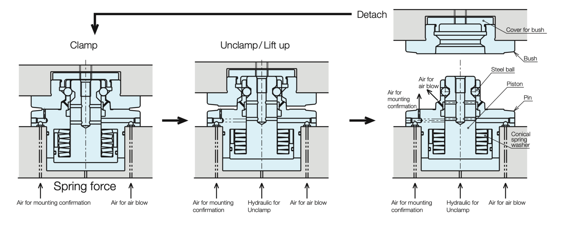
การใช้งาน
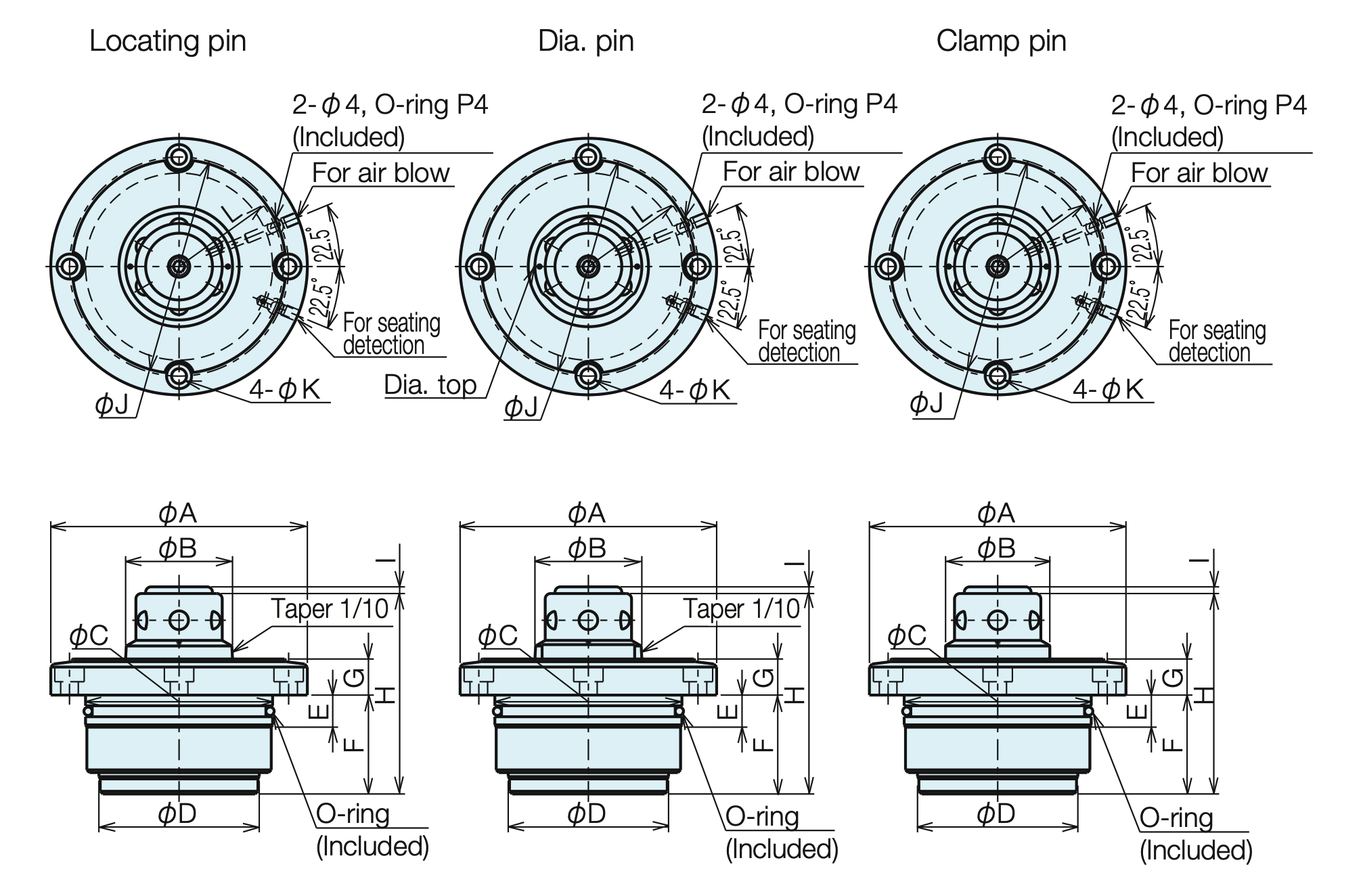
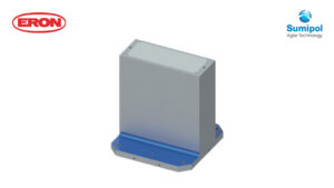
ขนาดการติดตั้ง
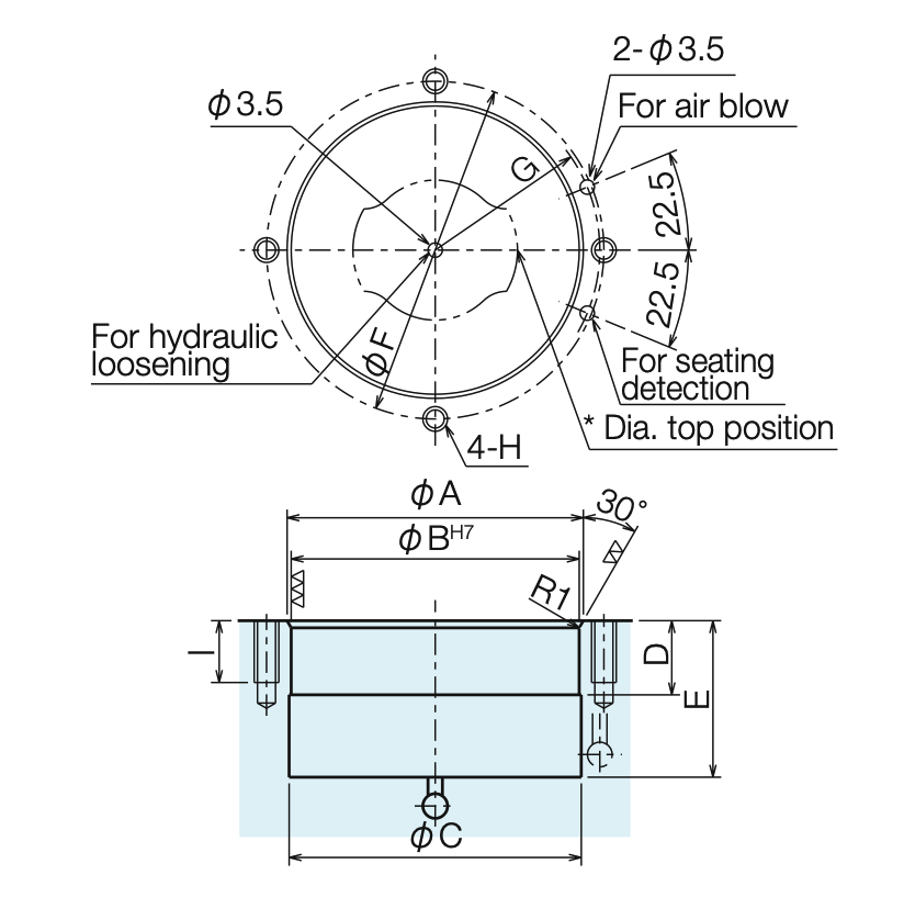
| A | B H7 | C | D | E | F | G | H | I | |
| QLSM03 | 46 | 45 | 44.5 | 12 | 32 | 54 | 27 | M5 | 13 |
| QLSM07 | 72 | 70 | 71 | 18 | 39 | 82 | 41 | M6 | 15 |
| QLSM10 | 92 | 90 | 91 | 20 | 45 | 102 | 51 | M6 | 15 |
| QLSM16 | 102 | 100 | 101 | 20 | 60 | 114 | 57 | M8 | 20 |
* The relationship between the dia. pin top position and the tap hole is as shown in
the diagram. Machine the tap holes and port holes according to the direction of the
dia. pin.
การเขียน
ข้อมูลทางเทคนิค
| Type | Hydraulic Type Single Action | ||||
| Drive Method | Clamping | Spring | |||
| Unclamp | Hydraulics | ||||
| № | QLSM03 | QLSM07 | QLSM10 | QLSM16 | |
| Clamping Force (kN) (at 5 MPa) | 3 | 7 | 10 | 16 | |
| Liftup Force (kN/piece) (at 5 MPa) | 1.7 | 5 | 9 | 10 | |
| Clamp Stroke (mm) | 1.8 | 2.3 | 3.1 | 2.6 | |
| Liftup Amount (mm) (at 5 MPa) | 1.3 | 1.8 | 2.6 | 2.1 | |
| Cylinder volume(cm3) | Clamp Side | – | – | – | – |
| Unclamp Side | 2 | 7 | 14 | 15 | |
| Minimum Operating Pressure When Unclamped (MPa) | 3.6 | ||||
| Guaranteed Withstand Pressure (MPa) | 10 | ||||
| Recommended Air Blow Pressure (MPa) | 0.5 | ||||
| Ambient Operating Temperature (°C) | 0-65 | ||||
| Normal Usage Pressure (MPa) | 5 | ||||