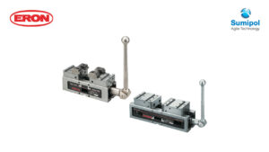
Clamping Method
(1) Clamping method by hydraulic pressure
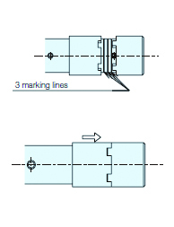
・With the matching parts of the switching collar and socket separated, rotate the handle in the clockwise direction.
・The jaw plates touch the workpiece, and the internal clutch engages with a clamping force of approximately 10 kN.
・After the clutch has engaged, only the handle and socket rotate, and the hydraulic clamping operation is performed.
・Clamping force and handle operation (after the clutch is engaged)
| Handle Operation 3 marking lines (Rotation) | 1 | 2 | 3 | 4 |
| Clamping Force (kN) | 12 | 20 | 30 | 40 |
* The clamping stroke by hydraulic pressure is approximately 1.8 mm.
(2) Clamping method by screw
- Slide the switching collar towards the socket side, and with the switching collar and socket interlocked, rotate the handle in the clockwise direction. (While interlocked, the clutch does not operate).
- Clamping by screw has a maximum of approximately 10 kN.
(3) Combination of clamping by screw and clamping by hydraulic pressure
- When clamping workpieces that deform easily and workpieces where the workpiece surface is a cast surface, perform clamping using the screw and then perform clamping using hydraulic pressure.
- Perform the clamping operation by screw as shown in (2) and then perform clamping by hydraulic pressure as shown in (1).
- The clamping force is (clamping force by screw) + (clamping force by hydraulic pressure).
- For workpieces where large deformation may occur, check that the workpiece is securely fixed after clamping.
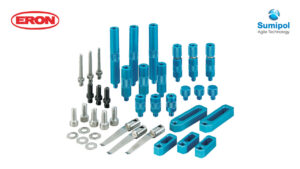
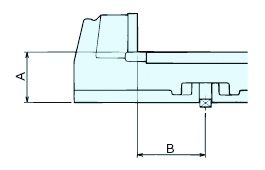
Parts Details
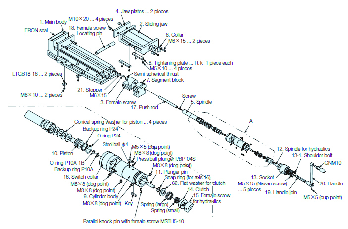
When ordering parallel productsA and B align within 0.01 no matter how many pieces
 Order multi-jaw specification products (suffix G)
When ordering, specify the groove width of the machine you are using.
Can only be manufactured when newly purchasing Matched specification products.
Accuracy Standards (Static Accuracy)
|
 |
||||||||||||||||||||||||||||||||